

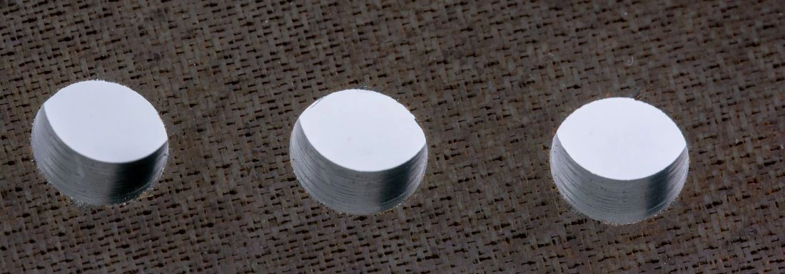
When CFRP drilling starts to delaminate, review these first, in order: the drill point geometry, the cutting data (cutting speed and feed rate), chip evacuation at the hole exit, and the condition of the drill's cutting edges.
Delamination damage is one of the most costly defects in the CFRP drilling process, because it usually shows up on parts already well into production. When it does, downtime is significant. Intermediate inspection is required, next steps have to be considered, and machine and processing time is lost. Delamination can be corrected, but it involves curing bonding resin into the affected area, often removing the part from normal production, creating an extra setup, and sometimes sourcing additional tooling to re-machine the corrected area of the carbon fibre-reinforced polymer (CFRP) part. Getting the drilling process right first time is far cheaper than putting it right afterwards.
Peel-Up or Push-Out: Know Which You Have
Delamination is the separation of layers in the CFRP structure, a failure between the plies at the fibre-matrix interface. In drilling, it happens in two ways: the lifting action of the drill bit as it enters the cut, or the pushing created by high thrust force as the drill nears the hole exit and the remaining material becomes too thin to cut cleanly. Entry-side lifting is peel-up; exit-side pushing is push-out. Knowing which you are seeing is the first step, because each points to a different fix.
The First Things to Review, in Order
Drill point geometry
Choosing the correct drill point geometry is one of the most effective ways to prevent delamination when drilling composite materials. Many drill bit designs put less stress on the material as they cut, using tool materials that keep the drill in good condition for longer. Point angles for CFRP are typically smaller than those on production drills for metals, and angles as low as 90 degrees are among the most effective at preventing delamination and reducing thrust force. Drill diameter matters too, as thinner sections leave less material to resist the cut.
Cutting data and chip evacuation
If delamination appears at the start, look into the drilling strategy. Check the cutting speed and feed rate, and make sure chips are being cleared efficiently from the hole. High thrust force pulls at the material, lifting layers on entry or pushing the plies apart at the hole exit. Reducing the cutting data lowers thrust force, which lets the material be cut cleanly rather than deflected.
A soft start or soft exit
Consider whether reducing the feed rate would benefit a soft start into the operation, or a soft exit on a through hole. Easing the feed at these points takes the force out of the two moments where delamination is most likely.
Drill wear
If delamination appears mid-process, where a number of good holes have been machined and then it suddenly occurs, inspect the drill bit's cutting edges for signs of tool wear.
One Bad Hole, or a Systemic Problem?
It is not practical to inspect every hole produced. The answer is to develop best practice and optimise the drilling parameters so the process is as secure and repeatable as possible, rather than catching delamination one hole at a time.
Adjusting the Process vs Changing the Tool
If you are seeing delamination from the outset and you are confident the correct drill design is being used, the focus should fall on the drilling strategy: check the cutting speed and feed rate, and decide whether the process would benefit from reduced thrust force, in part or across the full operation.
If the issue arises mid-production run, look at the drill's condition for signs of tool wear. Wear is a sign it may be time to change the tool. From there, you can set a reduced tool-life expectancy to create a safe end-of-life point, or reduce the cutting data to extend tool life. Both let you calculate a safe tool-change frequency, which should be rewarded with a secure, repeatable process.
Rules of thumb:
- Make any initial change to the cutting data large enough to produce a measurable change in result.
- A 15 to 20 percent reduction in cutting speed or feed rate, or in expected tool life, should be enough to change the outcome.
- A soft start or soft exit means easing the feed, and here a reduction of up to 30 percent can be enough to secure the process.
The Tooling That Prevents Delamination
Exactaform offers a range of specialised drill designs and cutting tool materials built to prevent delamination in composite materials:
- Drill point geometries that help prevent delamination and improve hole position accuracy, with multiple flute options for higher productivity.
- Diamond-coated range for low to mid-volume production.
- PCD-tipped ranges for volume production and the greatest tool life.
Diamond-coated tooling is the practical choice for lower to moderate volumes, while PCD earns its place on higher-volume work where maximum tool life matters most.
Frequently Asked Questions
What causes delamination when drilling CFRP? It is the separation of the material's layers at the fibre-matrix interface, caused either by the drill bit lifting the top plies on entry (peel-up), or by high thrust force pushing the bottom plies apart at the hole exit (push-out).
How do you prevent CFRP delamination? Start with the correct drill point geometry (angles as low as 90 degrees), keep thrust force low through controlled cutting speed and feed rate, clear chips efficiently, and use a soft start or soft exit where needed.
What feed rate should you use for drilling CFRP? There is no single number, but reducing the feed rate at entry and exit lowers thrust force. A 15 to 20 percent cut in feed rate or cutting speed, or up to 30 percent for a soft start or soft exit, is a practical starting point.
Diamond-coated or PCD tooling for composite drilling? Diamond-coated tooling suits low to mid-volume production; PCD-tipped tools are best for higher-volume work where the longest tool life is the priority.